How To Measure Audio Performance Of Electro-Acoustic Devices
There are numerous instruments, equipment, and electro-acoustic devices used in a wide variety of events and activities. Most people are familiar with these devices that they use every day or see in some of the events that they attend. Some examples of electro-acoustic devices that people use on an almost daily basis are mini speakers, microphones, earphones, headsets, loudspeakers, stereos, and amplifiers.
The part that most people aren’t familiar with is that it takes teams of professionals and sound engineers to ensure that the electro-acoustic devices that come out of manufacturing plants produce the excellent sound of the highest quality. To make sure that electro-acoustic devices meet the specific industry standards and requirements, sound engineers and audio technicians perform multiple audio performance tests on these instruments and devices.
You can check it out https://www.ap.com/audio-analyzers/ and other similar sites if you want to know more about audio performance tests are done. Here’s a brief article on how to measure the audio performance of electro-acoustic devices.
Table of contents
How Audio Analyzers Measure Audio Performance?
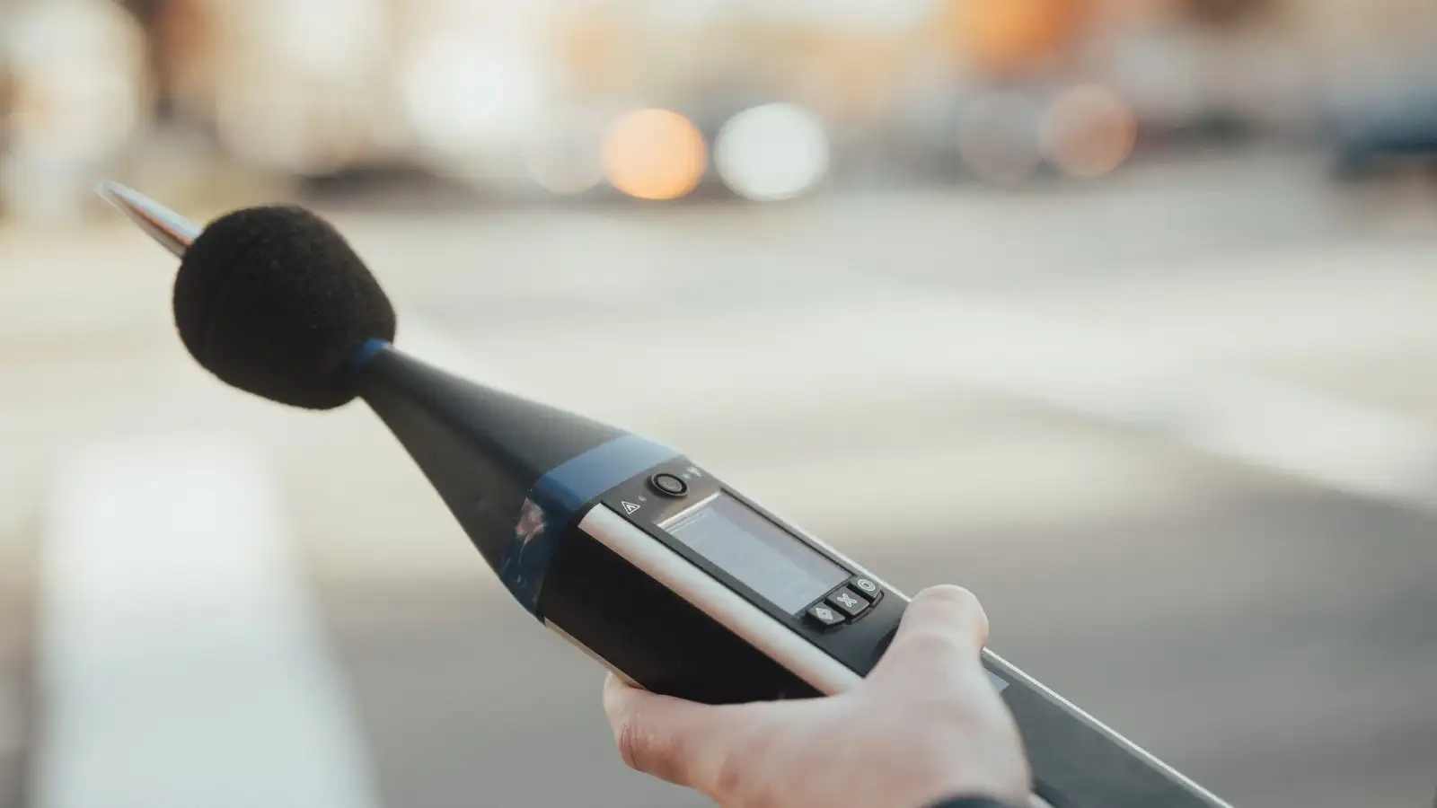
The equipment and devices used to test and measure the sound quality and audio performance of electro-acoustic devices are called audio device analyzers. This testing equipment is used to measure the audio performance of various sound equipment and other electro-acoustic devices and instruments. Audio device analyzers can be used in a wide variety of ways to test and measure audio equipment, instruments, devices, and gadgets.
One of the most common applications of audio device analyzers is to test the quality of the sound being produced by stereos, speakers, loudspeakers, microphones, mobile phones, voicemail apps, and other electronic audio devices and electro-acoustic devices. What these audio device analyzers do is measure the strength and the quality of the signals being produced by these electronic and electro-acoustic devices.
In some instances, the audio device analyzers would have to make use of special software applications and sound cards to execute their tests on device performance and sound quality.
The way it works is that the audio device analyzer will send a test signal to the device being tested or what audio technicians call device under testing (DUT). In response, the DUT would emit a signal which is its response to the test signal transmitted by the audio device analyzer. The audio device analyzer’s operator would have to compare the output signal of the DUT with the original test signal transmitted by the audio device analyzer.
The special software application of the audio device analyzer would then analyze the DUT’s audio performance. It does this by detecting the distinction and difference between the DUT’s output signal and the original test signal. There are several operational indicators and standard parameters used to come up with the audio performance analysis.
Here are some of the standard parameters used in the audio analysis:
- Gain
- Signal-to-noise ratio (SNR)
- Total harmonic distortion plus noise (THD+N)
- Crosstalk
- Phase
How Do Audio Performance Measure

1. Thiele-Small Measurement
The Thiele-Small test measures the complex impedance of a loudspeaker. It also delivers calculated electromechanical parameters. These parameters are used to test loudspeaker drivers to find out if there’s low-frequency performance.
The results from the Thiele-Small tests are used to describe how the enclosure and loudspeakers interact with each other. These are typically accurate descriptions that are vital to the tests which are done during both the design and production stages of loudspeaker systems.
If the test results come out with a measured deviation from the expected Thiele-Small parameters, this is to identify if there are any defects in the quality of the device parts. It’s also used to identify manufacturing defects.
Some of the methods used by the Thiele-Small measurement test are the Known Mass, Known Volume, and Added Mass methods. Known Mass is a method that is used to come up with Thiele-Small characterization in a single pass. On the other hand, Known Volumes and Added Mass use two-pass measurements. These two measurements deliver accurate parameters.
2. Rub & Buzz Detection
Another test used to measure the performance of electro-acoustic devices is the Rub & Buzz Detection. This test employs a chirping stimulus. It’s used to identify defects that involve a high peak ratio coupled with a high crest factor.
Some of the typical defects identified by Rub & Buzz Detection include particles in the voice coil that might have already become misaligned. It can also detect if some suspension elements aren’t completely fixed to the frame by adhesive components.
The human ear is highly sensitive to these buzz noises, even though they’re quite hard to detect using FFT and other standard detection techniques.
3. Air Leak Detection
There are also audio testing devices that can detect and measure air leaks and defects. For example, there are modulated noise measurement devices that use air leak defects to create a testing and measurement model. Air leak defects are modeled as some sort of weighted white noise.
A low-frequency stimulus is used to modulate the weighted white noise. This model has been successfully used to inspect enclosures and detect leaks. Typically, the causes of these air leaks are defects from the time of construction, open jacks, or poor seals. Air leaks have to be searched and identified because they can degrade the sound quality and performance of loudspeakers.
The presence of air leaks can harm how the loudspeakers were designed to function and operate. If there are any air leaks, this could produce unwanted noise. What makes it worse is that it’s quite difficult to detect unwanted noise interferences with the use of standard parameters and measurements. They’re often buried in the noise floor and it would be quite difficult to distinguish them from the rest of the noise.
Air leaks are becoming a greater challenge for designers and manufacturers of loudspeakers. Producers of compact integrated audio devices and products have been investing in research and development to continuously push the technological limits and boundaries of bass response and sound pressure. To achieve this high level of quality and performance, manufacturers and producers have to constantly test whether the enclosure of their products has integrity.
Some of the other things that contribute to the gaps in the enclosure integrity of loudspeakers are those controls and jacks which are mounted on the loudspeakers. The mounting is typically fixed by components that would have to bore or puncture holes onto the surface of the structure covering the enclosure. This is one of the things that make it hard to manufacture and produce a leak-free enclosure.
What the audio test device does is that it executes the test by automatically computing the standard parameters of acoustic response. These standard parameters increase the response of the Device Under Testing (DUT) to the test signal or test stimulus. Here are some of the measurements calculated by the audio test device:
- Level of noise or sound
- Frequency response
- Distortion
- Phase
- Group delay
These acoustic responses are usually returned by the audio test drive as graphed measurements. There are audio test device models in the market today which can be used to perform Nth-octave smoothing and synchronous averaging. The measurement and testing results can be viewed on the screen. They can also be exported in a table format form which can be used in spreadsheets and other software applications. They can also be printed in purely readable formats such as PDF files.
4. Waterfall And Polar Plots
Some audio testing devices come with powerful visualization tools. These visualization and presentation tools can be used to gain a more in-depth understanding of electro-acoustic output patterns and electro-acoustic behavior. Some of these visualization tools are waterfall graphs and polar plots.
5. Waterfall Graph
The waterfall graph is a three-dimensional chart. The vertical coordinate measures intensity. The horizontal axis measures frequency. And the depth coordinates measure the angular offset. The waterfall graph measures the relative variance of the DUT’s sound compared with the original sound.
As frequencies go up, they tend to show intrinsic higher directivity. This means that most speakers tend to demonstrate weaker treble as you increase the offset. The practical implication is that electro-acoustic devices whose treble falls slowly tend to be ideal for listening because they exhibit the largest sweet spots. High-quality engineering devices will show a smooth, continuous surface on the waterfall graph.
6. Polar Plots
Polar plots or graphs measure the intensity based on the frequency. The relative intensity of the given frequency is shown as a function of the depth or the angular offset. The difference is that polar coordinates are used in the polar plots. This means that the measurements taken from the waterfall graph fit into a semicircle.
The reference measurement is the parameters of a semicircle. The practical implication is that devices that exhibit a test sound that closely resembles a semicircle have a large sweet spot. Speakers who are good for listening purposes will have smooth directivity curves.
7. Capabilities Of Advanced Equipment
The industry leaders in audio device analysis and performance testing technology typically integrate microphone power supplies with instrument-grade amplifiers. This is usually the preferred testing equipment and device of sound engineers, production test engineers, and designers. These professionals are highly skilled and often meticulous about the analytic equipment and testing devices that they use to gain a deeper understanding of how the microphones and loudspeakers they’re using perform.
Some of the most advanced state-of-the-art audio device analyzers and equipment have an industry-leading signal-to-noise ratio of 134 dB. They can also provide 20 dB of fixed-gain amplification. Some audio device analyzers can reach a frequency response of ±0.08 dB (DC-coupled). Other audio device analyzers have a residual THD+N of ≤ -106 dB (80 kHz BW).
The highest quality audio performance testers for microphones use pairs of unbalanced and balanced inputs to the microphones. This is applicable whether the microphones are being tested as DUTs or they’re being used as measurement microphones.
Conclusion
Audio testing of sound quality and device performance is crucial in making sure that electro-acoustic devices perform up to par with industry standards and requirements. To be able to achieve and maintain this, sound engineers and acoustic technicians perform numerous audio tests on electronic acoustic gadgets and electro-acoustic devices. These tests typically make sure of audio device analyzers that run special software applications to implement the sound quality and device performance tests.