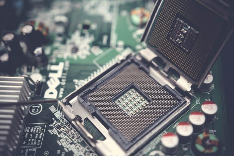
Computer design defines the structure and function of a computer system, just as architectural design determines the overall structure and function. Microcomputer components are designed to work together and this integration often plays an important role in System performance. Typical microcomputers include a microprocessor (CPU), bus, memory, parallel input/output, serial input/output, programmed I/O interface, and direct DMA memory access. The central processing unit (CPU) is the “brain” of the computer and is responsible for receiving data from input devices, processing data as information, transferring data into memory, and outputting.
The CPU has three main components.:
- Arithmetic logic unit (ALU)
- Control unit
- Registers
The function of the Arithmetic Logic Unit (ALU) is to perform arithmetic functions such as input, subtraction, division, and duplication, and logical operations such as AND, OR, and NO. The function of the control unit is the input/output control. It creates signals to control other computer objects, such as reading and writing signals and then commits fraudulent commands. Data is transferred from the memory to registers. The following registers convey information about rational performance and statistics to the ALU. The register is the fastest memory in a computer that holds information. When multiple cables carry the same type of information, it is called a bus. The most common buses on a computer are the address, data, and control buses.
Contents
What is Address Bus?
The address bus defines the number of addressable locations in a memory IC by using the 2n formula, where n represents the number of address lines. If the address bus is made up of three lines, then there are 23 ¼ 8 addressable memory locations. The size of the address bus directly determines the maximum number of memory locations that can be accessed by the CPU. For example, a CPU with 32 address bus can have 232 addressable memory locations.
What is Data Bus?
The data bus is used to carry data to and from the memory. Each location can hold only four bits. The size of a memory IC is represented by 2^n*m where n is the number of address lines and m is the size of each location.
The size of the data bus plays an important factor in CPU performance, the current CPU’s data bus is 32 bits or 64 bits, and a CPU with a 32-bit data bus means it can read or write 32 bits of data in and from memory. The early generation of CPU contains an 8-bit data bus, and each memory location holds one byte, for reading the word “book” as shown. The CPU requires to access memory four times.
By increasing the data bus from 8 bits to 32 bits, the CPU can access memory and read the entire word “book.” Most CPUs offer instruction to read 1 byte, 2 bytes, or 4 bytes from memory.
What is Control Bus?
The control bus controls the performance of each component by passing control signals from the control unit to the computer components. In addition, the control unit receives control signals from computer components. Some of the control signals are as follows:
Read signal: The read-line is set to high to read from a memory location or input/output (I/O) devices.
Write signal: The write line is used to write data into the memory.
Interrupt: Indicates an interrupt request.
Bus request: The device is requesting to use the computer bus.
Bus Grant: Gives permission to the requesting device to use the computer bus.
I/O Read and Write: I/O read and write are used to read from or write to I/O devices.

